Valve World Magazine
A large volume and wide variety of hazardous and toxic materials are currently in use; coupled with increasingly stringent regulatory requirements this makes positive containment and control measures mandatory. Typical applications for so-called zero-leakage valves include thermic fluid, ammonia, chlorine, phosgene, butadiene, benzene, ethylene, hydrochloric acid, hydrogen, steam, fatty acid and Cat. M Fluids as per ASME B31.3, to name just a fraction of the many possible uses. Bellow seal technology is much spoken of as an ‘Absolute Zero” barrier to atmospheric leakage; a design that eliminates product losses, hazards to humans, the environment, and costly downtime required for packing maintenance.
By Rajesh K. Salins, Bell O Seal Valves Pvt Limited
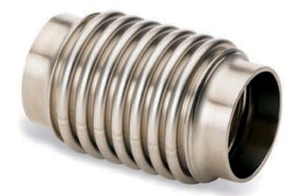
In a bellow seal valve the bellow is the main component. Metal bellows are thin-walled cylindrical components. Their surface area features a corrugated structure which is perpendicular to the cylinder axis. Because of this corrugated structure, the bellows are highly flexible during axial, lateral and angular deformation. At the same time, they are pressure-resistant, tight, temperature and corrosion-resistant as well as torsion resistant. The metallic bellow acts as a barrier between stem and secondary seal (i.e. a gland packing). Various manufacturing techniques are available, as follows:
Seamless
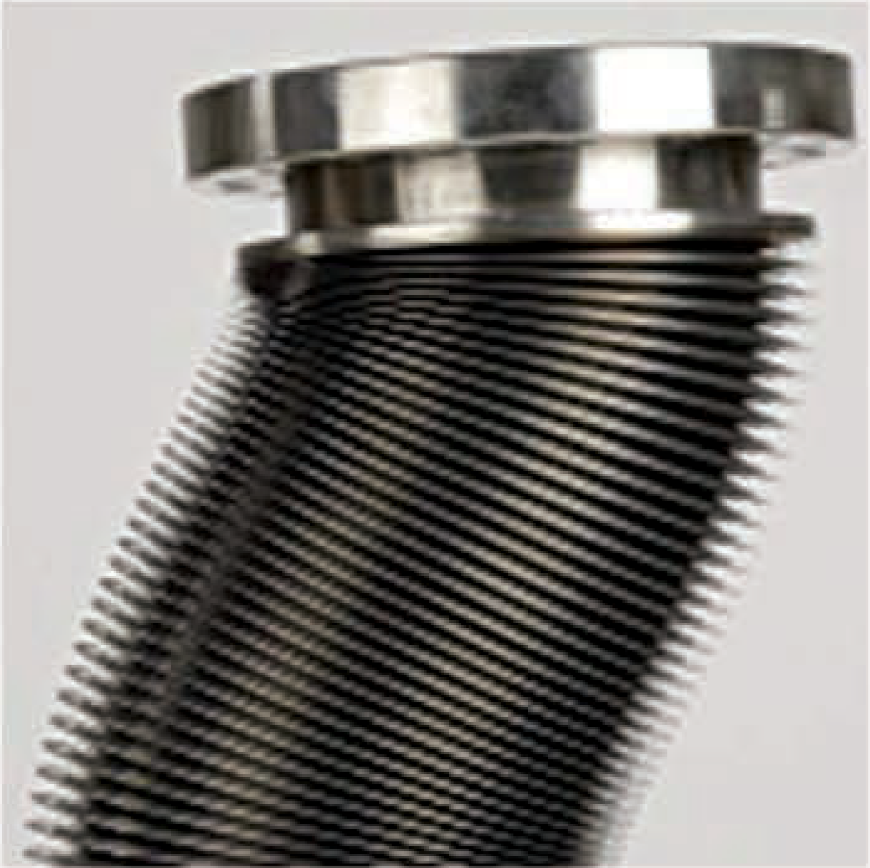
The seamless hydraulically formed bellow (see Figure 1) is manufactured from a thin tube. The seamless tube is manufactured using extrusion, piercing or gun drilling. The tube or cylinder is expanded outward to form the convolutions by hydraulic shaping. The bellow uniformity is achieved and the hydraulic pressure used to form the bellow inherently tests the bellows material for defects during manufacturing.
There is a limit on the length of the bellow that can be manufactured by hydraulic forming. This means that in gate valves (with their large lift requirements), two or three bellows welded in series will be needed to support the total valve stroke.
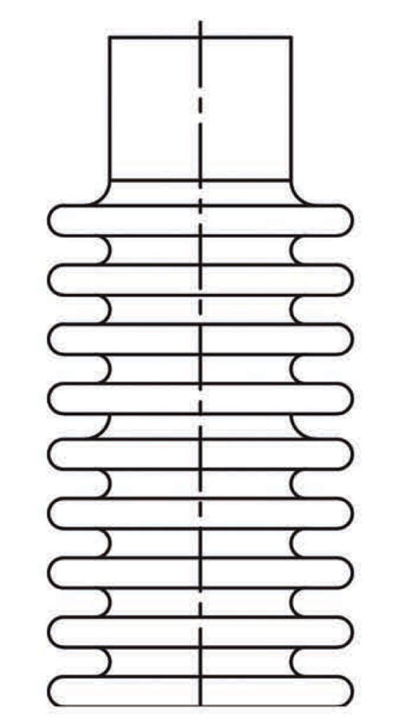
Welded roll
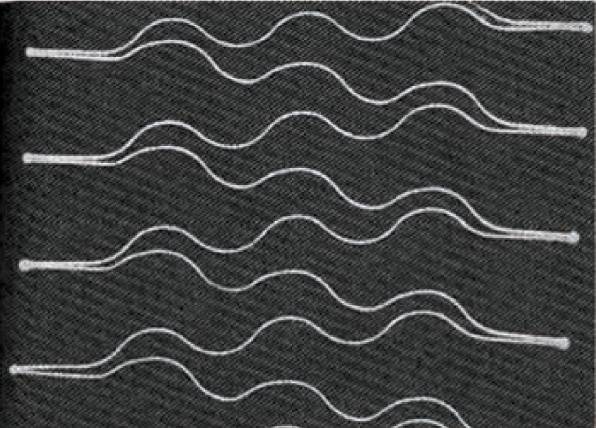
Welded roll formed bellows (see Figure 2) are widely used. In this process, thin sheet material is rolled into a tube and seam welded using a micro plasma welding machine. The bellow uniformity is achieved and the hydraulic pressure used to form the bellow inherently tests the bellows material for defects during manufacturing.
Welded bellow
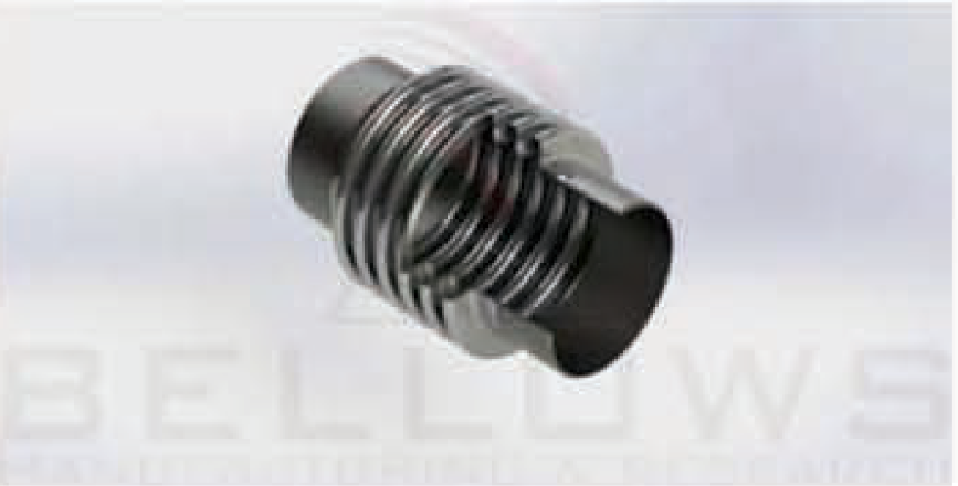
A welded below (see Figure 3) is made from a multiple stack of diaphragms circumferentially welded together at the inside and outside edge of each convolution (see Figure 4). A minimum of nine welds would be required to make a single-ply bellows with five convolutions Such a bellows can normally sustain greater compression and extension (stroke) than other bellows designs leading to a more compact bellow seal valve. It is more expensive and its performance is heavily dependent on the reliability of the welding process used in the manufacturing of the individual convolutions of the bellows.
Cycle life
The bellow seal design length must be such that the total number of convolutions will support the full stroke of the valve. Each convolution of a bellow, shares equal load in the total length of a bellow. The cycle life of a bellow is influenced by the length of its stroke. The stroke should be an in-line mode.
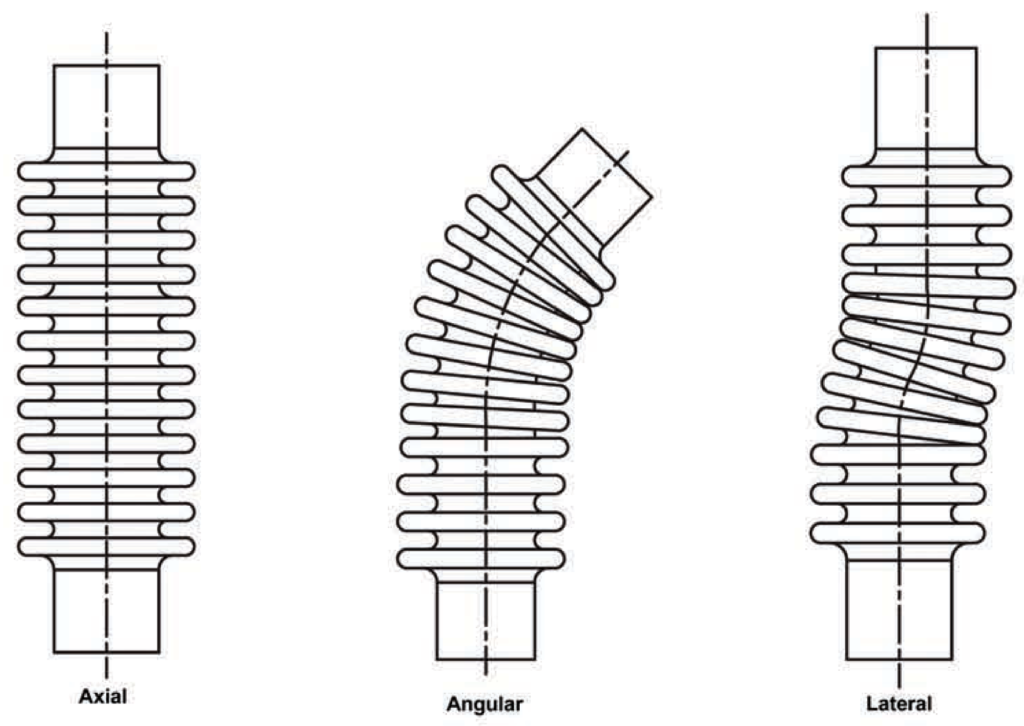
Lateral or angular movement in a bellow design reduces cycle life of the valve (see Figure 5). A bellow can be made to fail merely by stroking. Over-stroking of a bellow beyond its limit reduces life tremendously. Conversely, the cycle life of a bellow can be greatly improved by reducing its stroke.
In bellow seal gate and globe valve designs, it is important to keep the bellow spring rate as low as possible The lower the spring rate, the lower the hand wheel torque required just to flex the bellow and the longer the life of the valve. Over compressing a bellows can lead to convolution damage and low cycle life. Most bellow support load better in compression than in expansion. In addition to stroke, cyclic pressure on the bellow is another factor that affects cycle life of a bellow.
In a bellow seal gate or globe valve, the stress change in the bellow is a function of the valve stroke and the differential pressure experienced by the bellow during its stroke. If the valve is not stroked, then the only stress change in the bellow is due to the differential pressure experienced by the bellow during its life. The bellow cyclic life could be infinite if the bellow endurance strength is not exceeded during pressure fluctuation. If the bellow is stroked while the pressure on the bellows remains constant, the cycle life is expected to be better than if the pressure fluctuates widely. This is a major consideration when comparing advertised cycle lives of bellows valves from various manufacturers. The comparison of test data on cycle life for bellow valves should be made on the basis that all bellows are pressurized to a common pressure stroked to the full stroke requirements of the valve in which they are to be used. The cycle life of a bellows valve is determined by flexing it to its full design stroke while exposing it to its full design pressure. A constant pressure during cycle testing is less severe than a highly fluctuating pressure.
Pressure retention
The pressure retention capability of a bellow is determined by thin wall tubing, and this capability must be carefully balanced with its flexibility and spring rate. Doubling the wall thickness of a bellows will increase

its pressure retention capability but will reduce its stroke significantly and increase its spring rate. The higher spring rate would lead to higher hand wheel torques just to mechanically stroke the valve bellow Valve and bellow designers balance pressure, flexibility and spring rate of the bellow by using a multiply design. The pressure that a bellow can withstand can be doubled or tripled by using two or three piles of martal wall (see Figunes 6 and 7) one wall thickness will withstand a certain pressure and compression/exparmion, a multiply bellow of the same wall thickness will withstand two or three times the pressure while maintaining the same expansion/ compression. Conversely, if a one-ply bellows has the wall thickness equivalent to a two-ply or three-ply, it will withstand the same pressure as the multiply bellows, but its stroke (compression/expansion) will be significantly reduced, while the spring rate is increased. Mutiple bellows are used in bellow seal gate and globe valve designs Typical single (plyl sheet thicknesses for bellows used in gate and globe vahes are in the 0.10mm 10 0.50mm range. This means that the bellows must be made of a material whose corrosion resistance greatly exceeds that of the valve pressure boundaries and interfacing the bellows into the valve design cannot violate this comosion resistance Interfacing the bellows into the vahe by welding must be done in such a manner that the corrosion resistance inherent in the bellows material is not affected. The effective thickness of the weld to interface the bellows into the valve and to create the pressure- tight barmer is expected to be no more than the thicknens of the bellows. The corrosion resistant membrane-thick bellows should not be welded directly to a cartion steel or alloy steel body, bonnet, dac, stem or transition plece. The stem and doc may be made of the same material as the bellows in small valves so in this case welding the bellows directly to the disc or stem is acceptable.
Limitation to use
There are a number of limitations that can be expected from a bellows ssal valve. They can be summarized as follows:
Bellow cycle life: bellows have a finite life when used in valves that expose them to pressure fluctuations and full compression and expansion. As per MSS SP-117 a cycle is defined as fully open to fully clased to fully open. The bellows design shall be qualification tested in accordance with
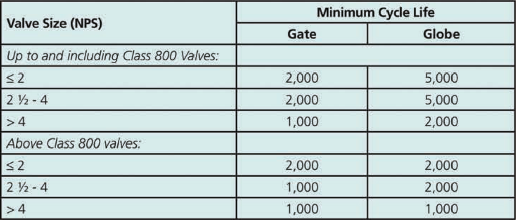
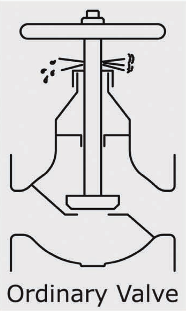
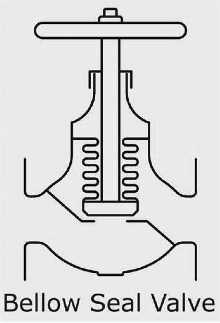
Table 1, unless otherwise agreed to by the valve manufacturer and end user.
Pressure retention capability
Since bellows are designed with the intent that thin wall formulas be used, bellows with membe thickness that provides flexibility and low spring rates are the outcome. It is highly unlikely that bellows can be designed to Interface with larger high pressure vakes that have traditionally used the thick wall formulas in designing of the pressure boundary. It may not be possible to design bellows for use in gate and globe valves that can retain high pressures while providing flexibility and a low spring rate, Especially in the case of clans rating above 2500.
Corrosion control
The selection of the material for the bellow will be critical Matching of service to the bellow material will require greater caution because unlike the pressure boundary of a valve, there isথ্যে। inherent comcsion allowance in the below of a bellow seal valve. Bellows are typically available in 31671, 321 stainless steel, inconel
625, Incoloy825 and Hastelloy C276.
Dimensions
Bellow seal gate valves will have a much greater height than conventional gate valves. The bellows must be designed to accommodate the high stroke requiremen of a gate valve. This leads to a long bellows thut requines the bellows gate valve to be eidended, impacting on piping configuration and layout.
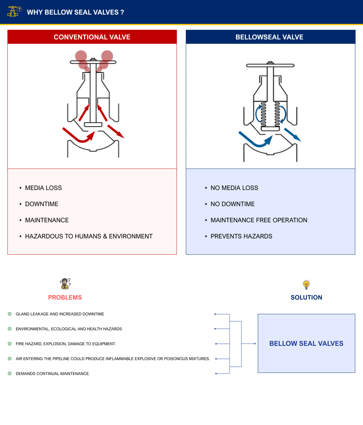
Gland leakage
One of the most frequent and serious problems valves face in gland leakage, results in wasted and increased plant downtime. Apart from the high cost of energy lasses, gland leakages can also cause serious environmental, ecological and health hazards to plant workers, Leakage of sensitive material can ho constitute a fre hazard, explosion, or damage to equipment by corrosive matenal. Air entering the pipeline could produce inflammable explosive or posonous mixtum. As gland packed valves often require continual maintenance, this can lead to difficulties if there is restricted access. A bellow ssal valve is a solution to zero inakage to the atmosphere (see Figures 8 and 9).
Economics of use
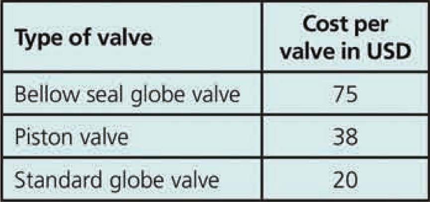
To analyze the cost benefits of a bellow seul globe valve as compared to a piston valve or a conventional gate/globe valve we will consider a 15mm valve operating with steam at 150 psc, in three types of valve Three types of cost need to be considered the capital, cust, the maintenance cost and the cost caused by the loss of energy media.
A) Capital cost the per unit cost can be estimated as follows:-
B) Maintenance cost:- assuming that gland leakage will begin within a penod of s months in a standard globe valve and in a period of nine months in a piston valve, then the maintenance costs will be as follows:
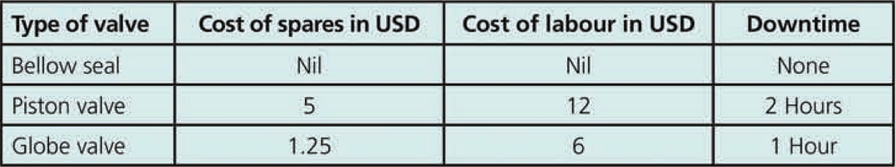


Assumptions: spare piston rings cast USD S per pair, a gland packing costs USD 1.25 and labour costs for maintenance are USD E per hour
Cost of downtime & energymedia loss We will assume a gland clearance of 1 thou (0.001 inchesi for estimation of gland leakage and a cost of USD 20 per ton of steem Steam will escape at a rate of 25 bohr through thin clearance (as per steam tables
If we assume a leakage rate of 11 kgs of steam per hour this means 264 kgs of steam loss per day or 7920 kgs per month Given a cost of USD 20 per ton of steam this equates to energy losses of roughly USD 5 per day or USD 160 per month which can be saved!
C) The cost of downtime is priceless and a value as such cannot be put on it. It can vary from a few hundred to millions of US dollars per day.
D) Total cost of ownership (TCO) for a twelve month period (alt figures in USD)
Since we have assumed leskage will begin after nine months
Since we have assumed leakage will start after six months
Based on Tables A, B and C, we can now calculate the total cost of ownership for all three values types over a twelve month period. This is based on the following assumptions
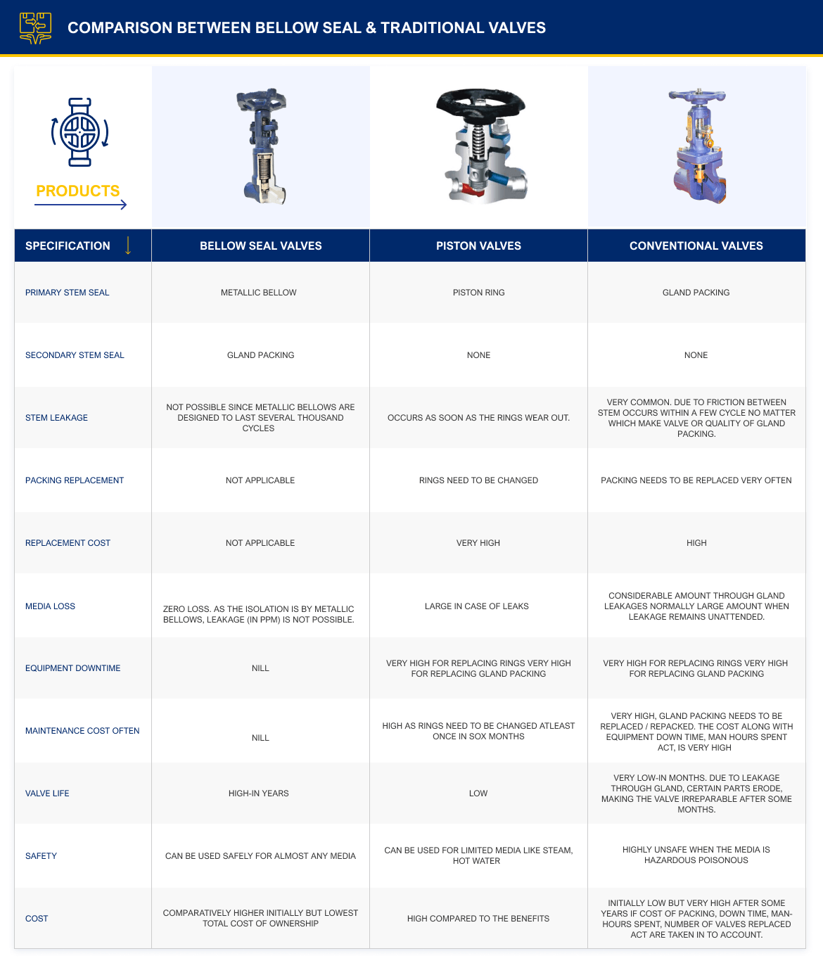
Comparison table
it is now possible to summarize the poutives and negatives of the hellows design as compared to piston valves and conventional valves in a table, as follows
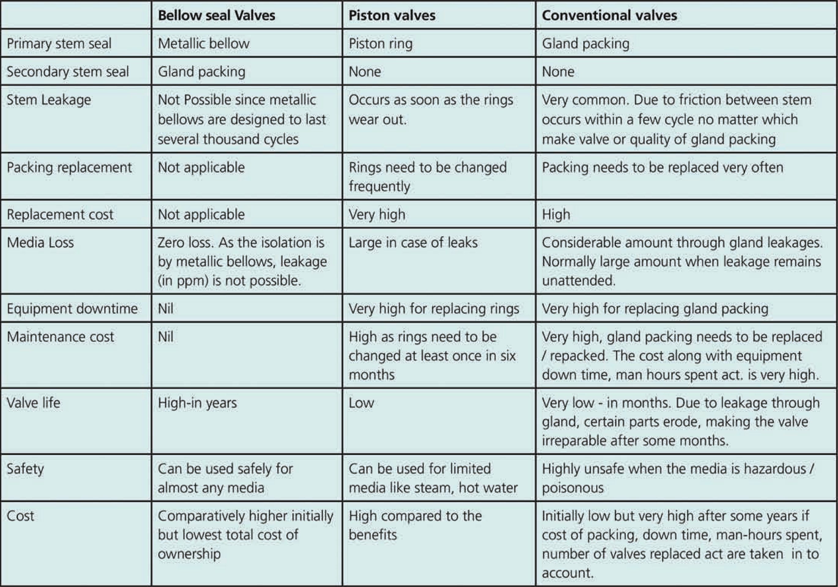
Note: figures indicated may of course differ front user to user and country to country in terms of the cost of the valve, the cast of steam generation, etc
Some parts of this section follow the analysis as indicated by Witzenmann GmbH.
About The Author
Rajesh K. Salins is the managing director at Bell O Seal Valves Pvt Limited, instrumental in the manufacturing of zero leak to atmosphere globe and gate valves.